| Input Ratings | Power Supply Allowable Variation | 3 Phase, 415v, 50Hz Voltage: +/-10% Frequency: +/- 5% Imbalance in power supply 3% Or Less |
| Output Ratings | Output Voltage Output Frequency Overload Capacity | 3 Phase, 415V 50/60/100/120/150/180/200/240Hz 150% of rated current for 1 min |
| Control Specification | Control System Freq. Control Range Torque boost Accel./Decel./time | Sinusoidal Wave PWM 2 to 240 Hz 16 selectable modes 0.1 to 200 Sec (Independently adjustable) |
| Protection | Stall Prevention | When the Motor current reaches the maximum limit on accel./decel., the frequency change Is Suppressed, so preventing OC/OVtrip |
| Inverter trip and error messages | Overvoltage (OV), Undervoltage (LU), Over Current, Inverter heatsink over heating/ external thermal overload relay trip (OU), Electronic thermal overload relay trip (OL2), CPU error (Err3) ground fault for output terminals. |
| Inverter Indication | 7 segment Digital Display | Actual frequency setting data (function and data codes) |
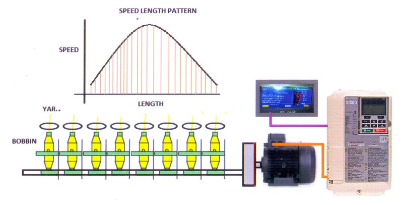
| Speed Time Pattern Generator Data | Speed-Time Pattern | 16 programmable speed-time patterns |
| No. of sections in each pattern | Each pattern can be programmed for 16 sections |
| Maximum cycle time | 48 hours |
| Resolution | One minute |
| Pattern Generator Indication | 6 Digit / 7 Segment Digital display | Motor Speed (RPM), Pattern data CPU error, Time elapsed in the cycle (Minutes) |
| Memory Function | | Data storage when intermediate stop occurs due to trouble or manual stop or power Interruption. On restarting, the speed and time will immediately return to the settings before stoppage. |
| Others | External Output Signal | End of cycle signal (1 from C, 230V AC, 2A) |
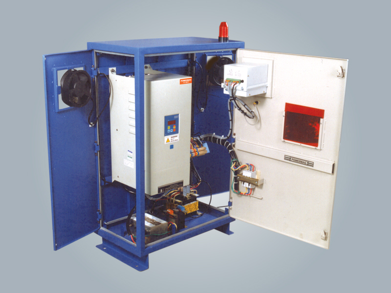
| Auto/Manual | Auto/Manual selections provided inside the panel. In Auto mode, control will be through pattern generator and In Manual mode the control will be through Inverter. |
| Bypass Facility | Bypass facility is provided to bypass Inverter. |
| Pneumofil Motor Control | Supply for the pneumofil motor and Interlock with Inverter is provided. i.e. Inverter will not start unless pneumofil motor starts. |
| Thermal Overload Relay | Thermal overload protection for main spindle motor In bypass mode and for pneumofll motor is provided. |
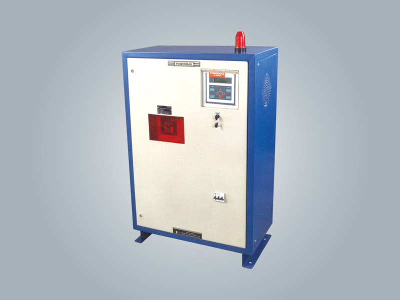
| Front Panel Indication | Power ON , Spindle trip, Pneumofil motor trip. Pattern generator 7 segment LED display for speed and time. Inverter 7 segment display. |
| Front Panel Controls | Inverter Reset, Inverter ON/OFF, pattern reset push buttons. |


